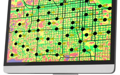
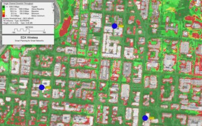
Public Safety wireless networks are a critical component in the operation of all national emergency services. P25 and TETRA are two different types of open interoperability standards used for public safety wireless systems and define the specifics of the underlying radio communication technologies. One benefit of using open standards such as P25 and TETRA, rather than using manufacture specific systems, is that equipment from different manufactures will be interoperable, increasing reliability while reducing overall system cost.
These technologies are a type of land mobile radio (LMR) system which also includes older analog standards. P25 and TETRA however, use digital modulation allowing both voice and data communication to be used on existing narrowband radio channels. Designing these new digital radio networks requires careful planning to provide high levels of performance and reliability while also being cost effective.
P25 and TETRA Network Planning
When you run a P25 or TETRA system RF study in SignalPro, the program will extract terrain and land-use (clutter) data, calculate signal levels, and build a composite area study grid in the same way it does in the main program for any type of transmitter or network.
Both P25 and TETRA networks are composed of digitally modulated radios that multiplex users onto a radio channel using TDMA (Time Domain Multiple Access) methods. There can be one or more radio channels in use in a particular area by one or more transmitters. Channel bandwidth is typically 25 KHz, 12.5 KHz or 6.25 KHz. Signal coverage is always limited by the receiver’s signal threshold (sensitivity) as well as interference from other transmitters using the same channel or adjacent channels.
Entering Equipment Information
Before studies can be run, you must first define your equipment within the EDX program. Entering specifications for transmitters is relatively straightforward. Transmitter power, antenna system gains and losses, antenna types and antenna heights are the basic parameters that determine the effective power radiated from the antenna into the surrounding coverage area. The frequency entered for each transmitter is the nominal value used by the propagation model to determine path loss and Fresnel zone clearance for that transmitter.
Receiver parameters for both the Base Transmitter and the Mobile unit are also relatively straightforward. Antennas and transmission system gains and losses need to be entered and then the noise at the receiver needs to be determined. This level can be automatically calculated within the Receiver Parameters dialog box in the program by entering the channel bandwidth and the overall noise figure for the receiver and antenna system.
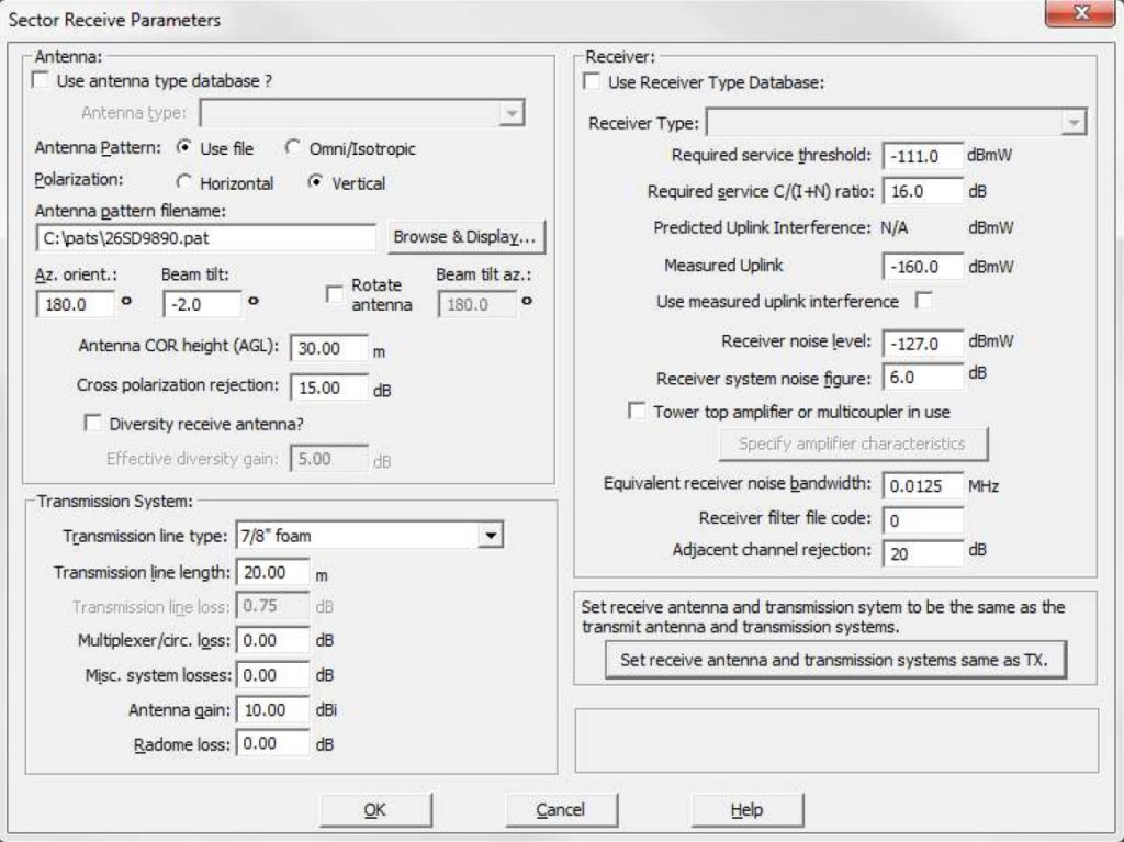
For Base Site receivers the use of a tower top amplifier or multicoupler is supported. There is a special entry box for this which will help to calculate the effective system gain as well as the effect on system noise. EDX software predicts thermal (“kTB”) noise at the receiver. For many systems, especially collocated and VHF systems, there is a higher level of externally-generated noise than internally-generated thermal noise. If the measured noise level at the receiver input is known, it should be entered as the “Receiver noise level” for the receiver.
Starting a P25/TETRA System Design
SignalPro stores information for a study in “.XML” files the project directory. The project files contain all the parameters and other information needed to completely reproduce a study map on your screen when you open a selected project. The project includes the specific parameters for each of your transmitter sites/sectors, or links, as well as information about the databases, propagation models, and base map features.
“Tuning” Simulcast delays
Simulcast is when you use multiple base stations operating on the same radio channel to enhance coverage in overlap areas. Since this can have both coverage and capacity improvements, it is commonly used instead of multicast (each base station using separate channels). In order for simulcast coverage to be useful, the signals that arrive from multiple base stations must be above the receiver signal level threshold and they must arrive within a narrow window of time in order to not create inter-symbol interference. Weaker signals (those that are lower than the received signal level from the strongest base station minus the simulcast capture ratio) don’t enhance or degrade system performance.
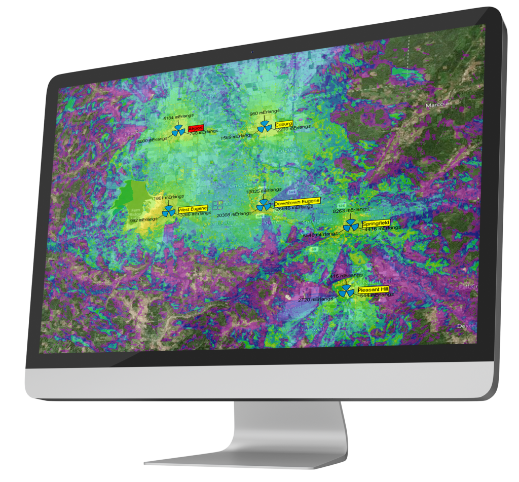
This often requires tuning of the simulcast delays, especially for systems that use tall sites and/or have a large coverage area. For example, here is a Simulcast RMS delay spread study plot for a UHF P25 system before the simulcast delays were tuned (all set to 0):
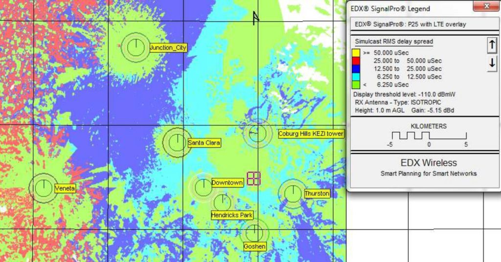
The areas with highest simulcast delays are in the western portion of the coverage area and are due to the strong signals from a mountaintop site in the east (Coburg Hills KEZI). The simulcast delays at each point can be queried for a more refined analysis.
Basic Studies
For study and analysis of basic system performance the equipment information described in the previous section about equipment parameters is sufficient. The following list shows the types of basic studies for which this information is sufficient:
- Shadow Map (Line-of-sight)
- Minimum Remote AGL
- Path loss between base and remote
- Received Power
- Field Strength
- Received Voltage
- Strongest (most likely) server
- Received power at best voting receiver
- Number of base receivers with power above threshold
- Number of servers at remote
- Number of servers within capture ratio
- Simulcast RMS delay spread
- Maximum simulcast delay spread
- Aggregate power flux density
What this means is that whether you have a traditional FM two-way system, or a digital P25 or TETRA system, or any other type of radio system, these basic studies can be run by simply knowing the base and remote transmitter ERP (effective radiated power), the directional radiation characteristics of all antennas, and the base and remote receiver antenna system gain/loss. Modulation type, digital coding, channel bandwidth, noise and interference or other unique system parameters are not necessary for these studies and are not used.
After you set up your terrain, clutter and optional building databases and choose the settings for your propagation model these basic studies can be run and displayed on the EDX SignalPro map. Note that the frequency entered for each transmitter is the nominal value used by the propagation model to determine path loss and Fresnel zone clearance for that transmitter.
Studies Using Noise and Interference
EDX SignalPro also provides a number of other studies that require the consideration of noise and interference in order to give a correct result. In fact, one could say that it is these type of studies that show most clearly how a proposed P25 or TETRA radio system will perform since the ratio of signal (or carrier) versus noise plus interference (“C/(I+N)”) at the receiver is actually what determines the ability of the receiver to successfully decode the modulated carrier. For example, in order for a traditional FM modulated signal using a 25KHz channel to be received with at least an audio quality of 20dB SINAD (TIA-TSB88 DAQ of 3.4) the C/(I+N) ratio at the receiver needs to be at least 20dB. Listed in table A below are the approximate required C/(I+N) ratios for the modulation types used in P25 and TETRA systems

The following is a representative list of studies that need C/(I+N) in order to calculate the desired result. These are studies that can be useful in planning/analyzing P25/TETRA networks:
- C/(I+N) at remote
- BER (Bit Error Rate)
- Percent log-normal reliability
- Uplink percent log-normal reliability
- Uplink percent log-normal reliability using voting receivers
- TIA/TSB-88 studies. These are important for evaluating and ensuring P25 system performance during the development phase.
Available TSB-88 Studies in SignalPro include:
- TSB-88 Monte Carlo bounded area coverage
- TSB-88 Radius-of-operation overlap reliability
- Aggregate simulcast Monte Carlo reliability
- Simulcast delay spread using Hess’s calculation
For some of the studies listed above, it is necessary to know what is the minimum acceptable
C/(I+N) ratio at the receiver for acceptable performance. The is also known as “Required service C/(I+N)” value found in the Receiver Parameters in the EDX program. This value is the dB difference between the noise threshold of the receiver and the receiver’s service threshold. “Acceptable performance” is defined usually by the old SINAD value or the newer TSB88 DAQ (Digital Audio Quality) metric. You should determine what dB ratio is appropriate for your system and enter it into the Receiver parameters.
Interference Calculation
The noise calculation at the receiver is determined by the parameters you enter in the Receiver
Parameters dialog of the EDX program. The interference at the receiver is determined each time a study is run. Obviously the interference will vary depending upon the location of the remote/mobile unit. For a given mobile location, the signal from all transmitters is calculated.
Then, the signals from all those transmitters who are classified as interferers are power summed to determine the interference level at the remote receiver. If the remote unit has a directional antenna then the pattern shape of this antenna is used to attenuate interfering signals that are off-axis to the main beam of the antenna.
EDX programs take into account the following additional factors when analyzing interference:
- Channel center frequency – this is the frequency either assigned to the transmitter when there is no channel plan in use, or it is the active channel when a channel plan is used.
- Channel bandwidth – either the noise bandwidth of the receiver or the channel bandwidth of a channel if a channel plan is in use.
- Antenna pattern shape – as determined by the antenna pattern file.
- Antenna polarization – the remote unit is assumed to take on the same polarization as the
- transmitter providing service to the unit.
Using a Channel Plan
In SignalPro you can choose to use a channel plan that allows you to consider that a transmitter may transmit on several channels simultaneously. Our advanced network planning modules also include a feature to automatically choose channels for a transmitter by finding the best channel assignment for lowest system interference.
TSB-88 Studies
The U.S.A. Telecommunications Industry Association (TIA) has developed a standard known as TSB-88. In this standard, there are descriptions of various types of radio systems and suggested ways to determine the coverage and the quality of performance of these systems. The intent of this standard is to create a common understanding of radio system design and deployment so that all parties (owners, designers, installers and end users) can agree on what constitutes an optimally performing system. In this way it is similar to what the International Telecommunications Union (ITU) Recommendations are intended to accomplish.
EDX SignalPro contains a TSB-88 study module that contains several studies that are based on TSB- 88 recommendations. The primary study in this group is the “TSB-88 Monte Carlo bounded area coverage” which is used to determine what percentage of area within a service boundary meets certain TSB-88 Channel Performance Criteria (CPC). The other studies in this module are either based on TSB-88 Monte Carlo C/(I+N) calculation methods or are useful studies for P25/TETRA systems.
Automatic Frequency Planning
If you have EDX SignalPro with one of our add-on modules, you can use the automatic channel
planning function to have the program quickly come up with the optimum channel assignment(s)
for each transmitter in a multicast system.
Download the P25/TETRA Design in SignalPro White Paper Here
New to EDX?
EDX Wireless provides instant access to a full suite of network planning solutions. Our all-in-one cloud-based software provides instant access to all the tools needed for wireless design, maximizing productivity and providing first-rate service to your customers. Our solutions ensure networks meet performance and cost requirements for 5G, LTE, IoT, mmWave, CBRS, Smart Grid, Distribution Automation, in-building DAS and more.


